Bluetooth Controlled Vehicle
I've always loved tinkering and DIY, so when Berkeley sprouted a design institute, I jumped at the chance to take the Design Innovation Core classes, specifically, Prototyping and Fabrication. One of the ongoing projects that we're working on is designing and building a concept vehicle. The first stage was solidifying the mechanics of the vehicle movement and steering. The second stage added bluetooth control functionality. You can check out further development of this and some other class projects on my Hackster account!
Step 1: Chassis Concepts & Cardboard Prototyping
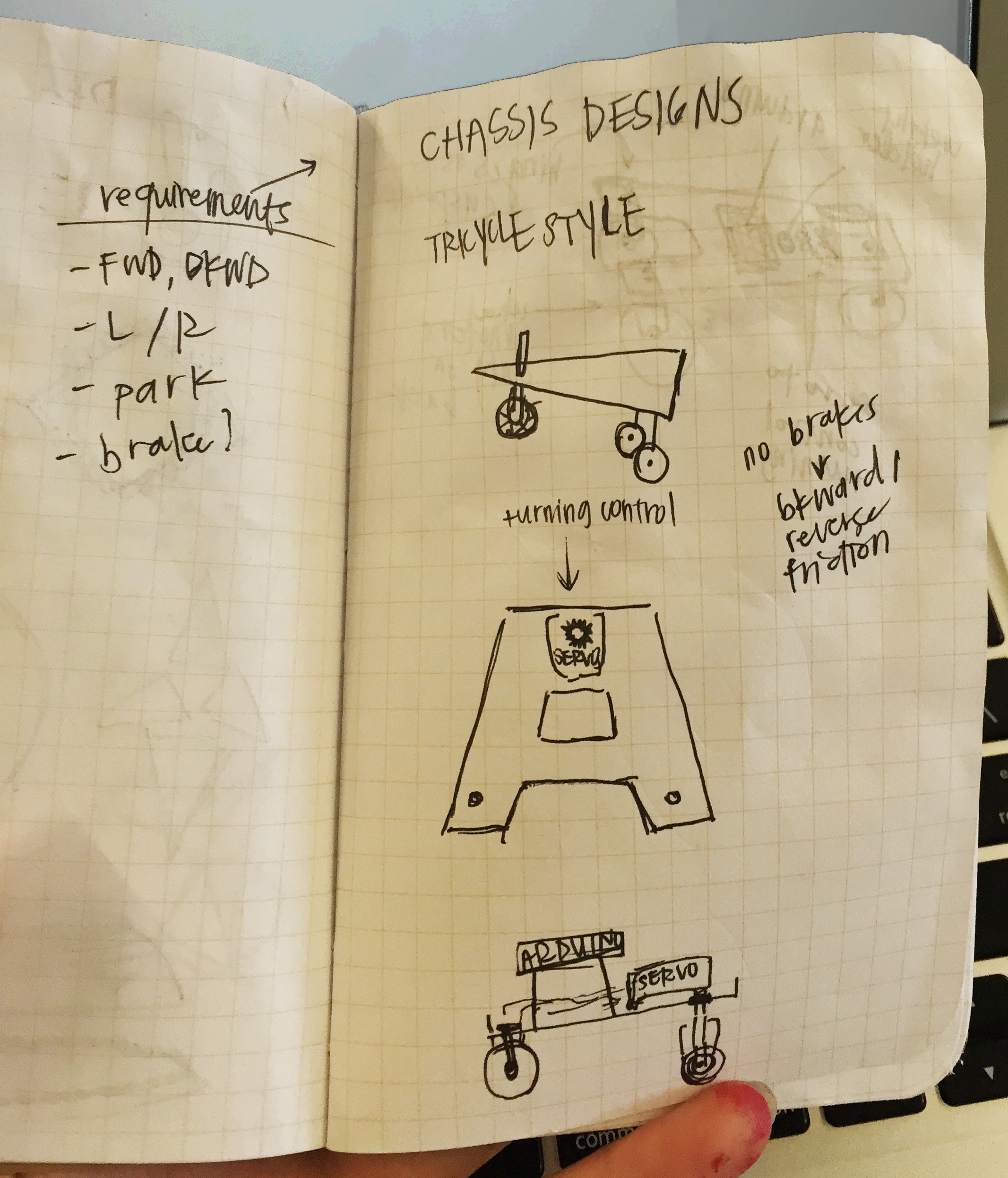
1. Tricycle Style
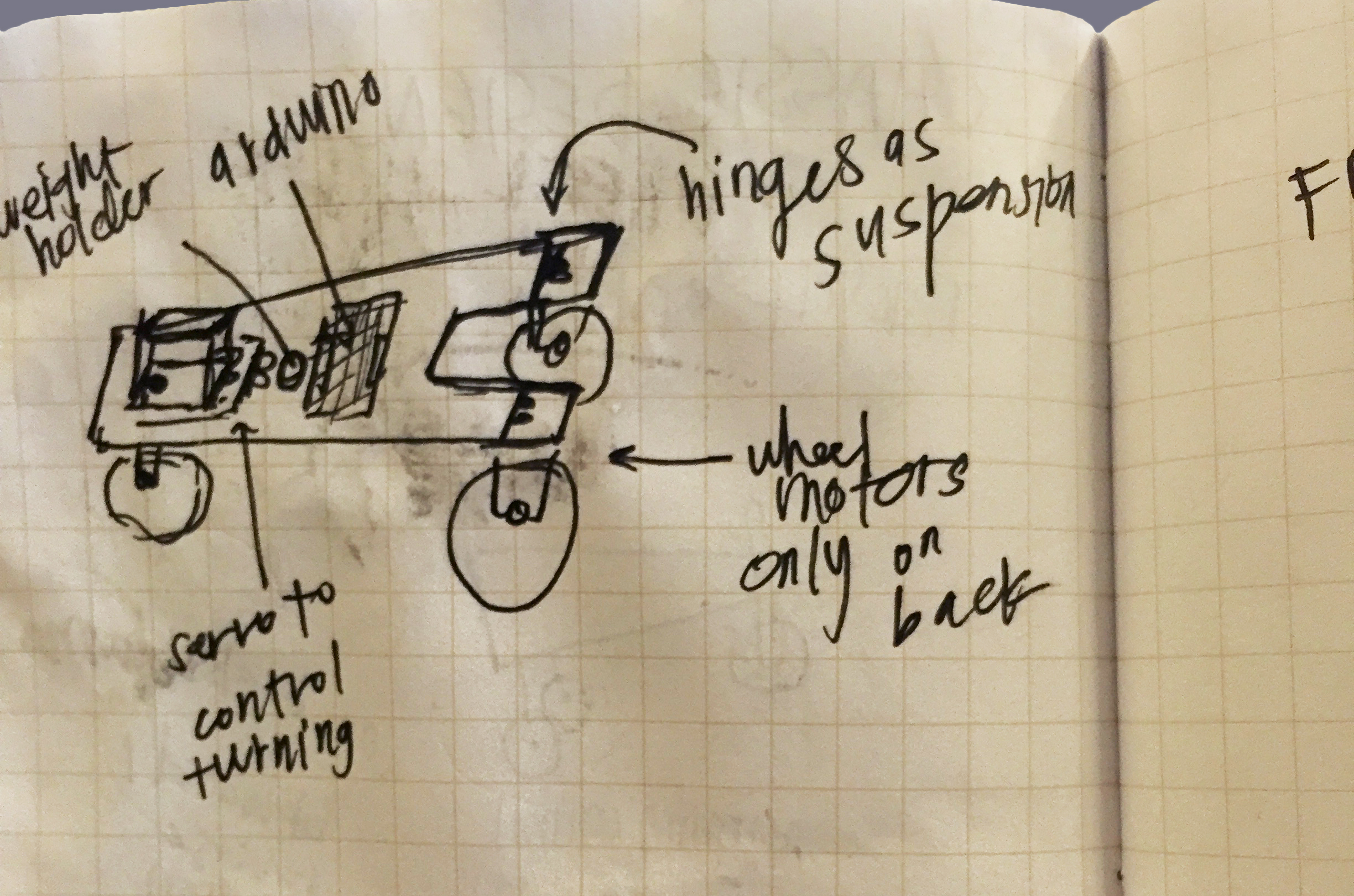
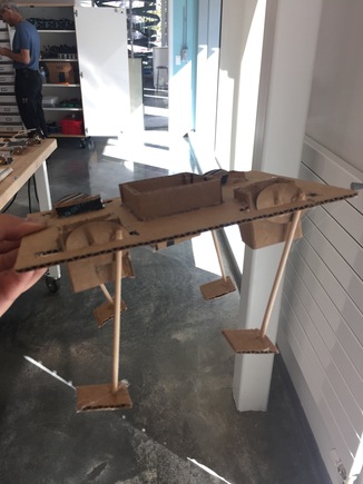
For my first chassis concept, I was inspired by the tricycle, using three points of movement. There is one steering module for the front wheel that will ideally be servo powered. The wheels in the back are hinged to the body to provide suspension for the chassis. Only the wheels in the back will be motor powered and the front wheel will be solely for steering. Bounding boxes for the battery and Arduino are on the bottom and top surfaces, respectively.
The sketches:
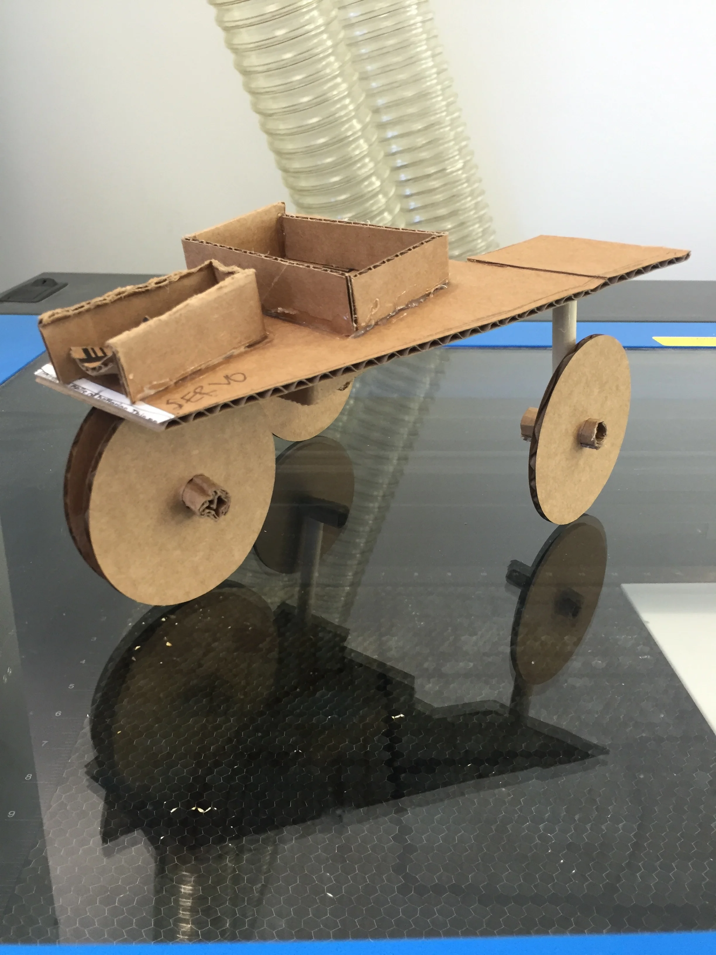
The cardboard prototype with functional pieces:
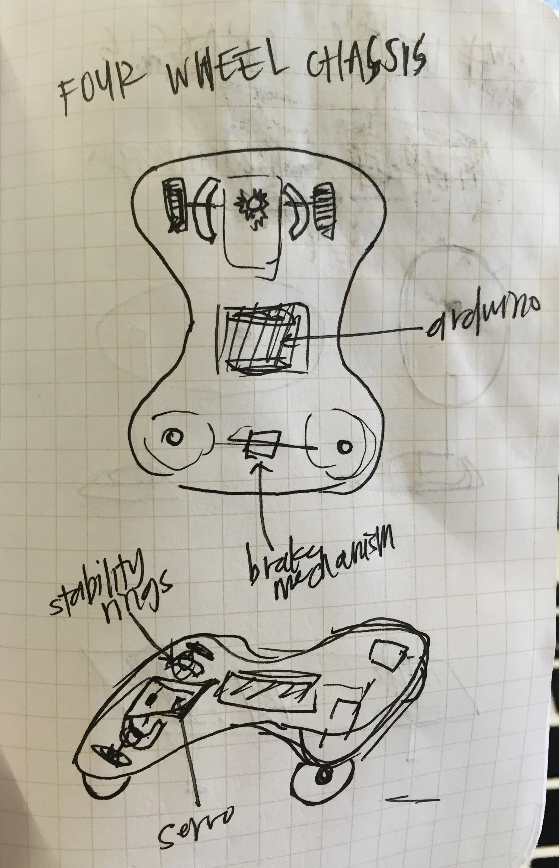
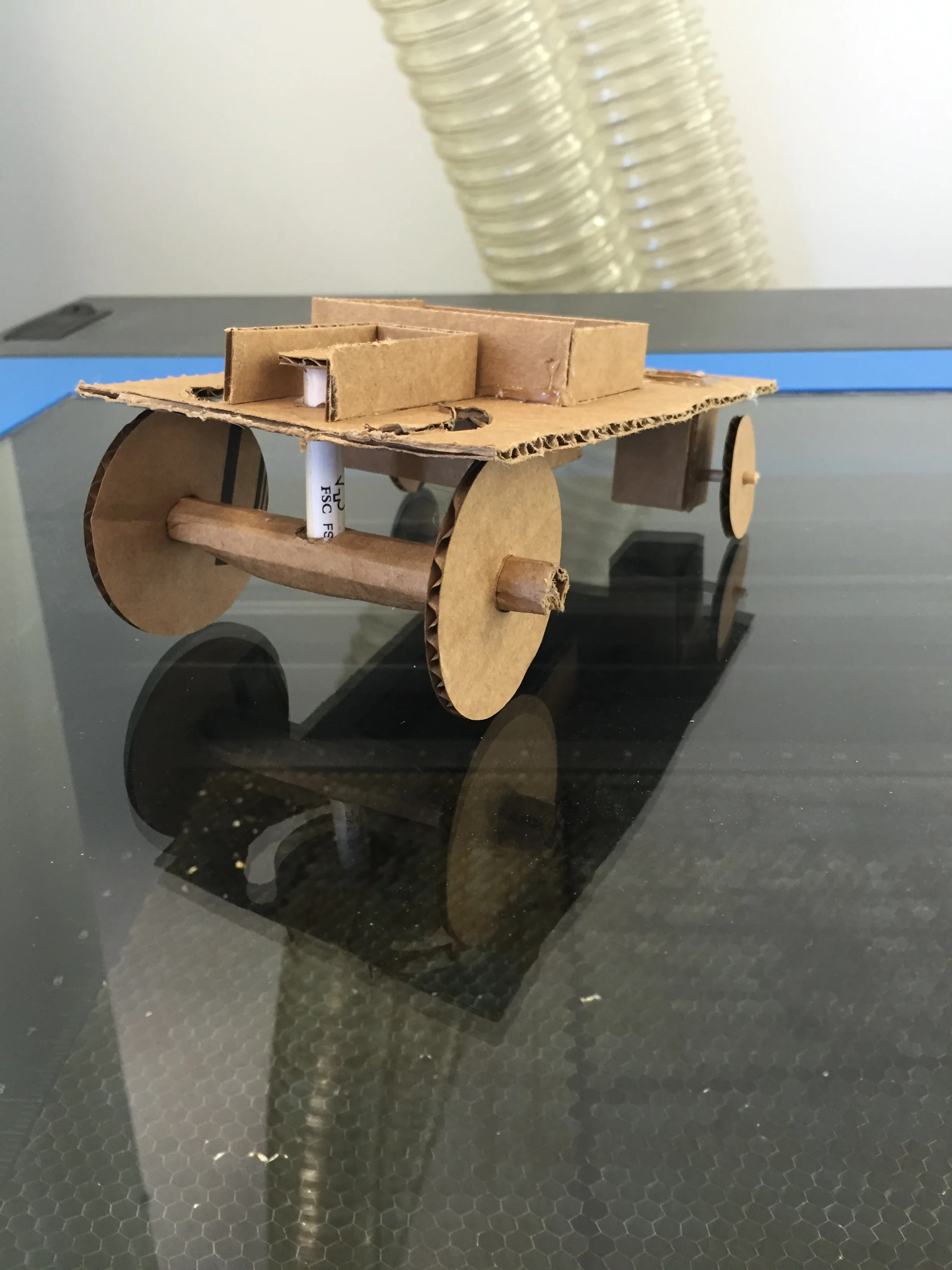
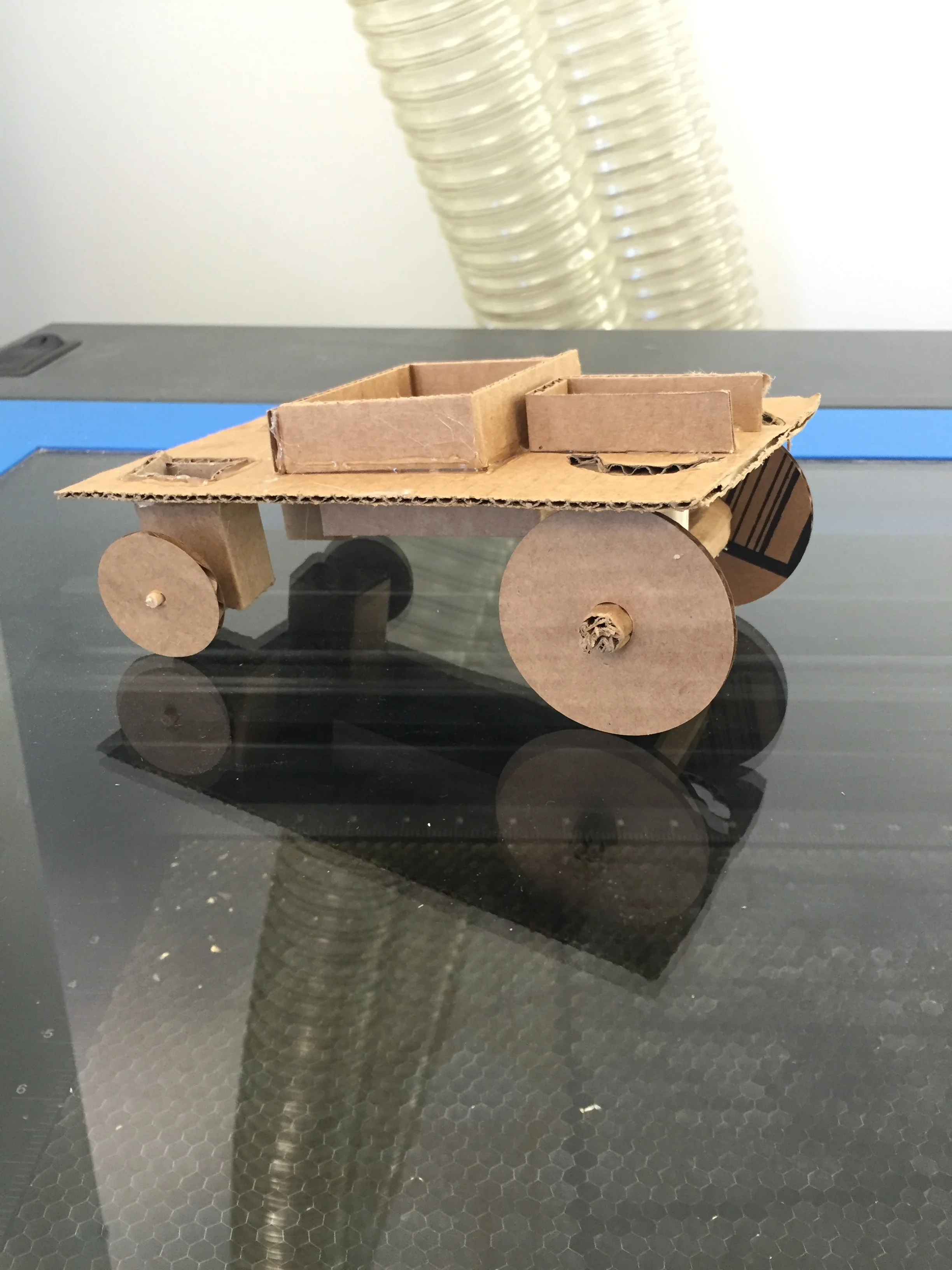
2. Classic Four Wheeled Chassis
For my second prototype, I chose to design a more traditional vehicle chassis. I stuck with the single steering mechanism for ease of syncing the wheel movement, but added some cuts at the top of the chassis. I envisioned guiding rods running through the holes to add stability to the front wheel mechanism, as one connecting point to the chassis did not seem too stable. The motored wheels will be in the back, as shown by the larger boxes attached to those.
The Sketch and Cardboard Prototype:
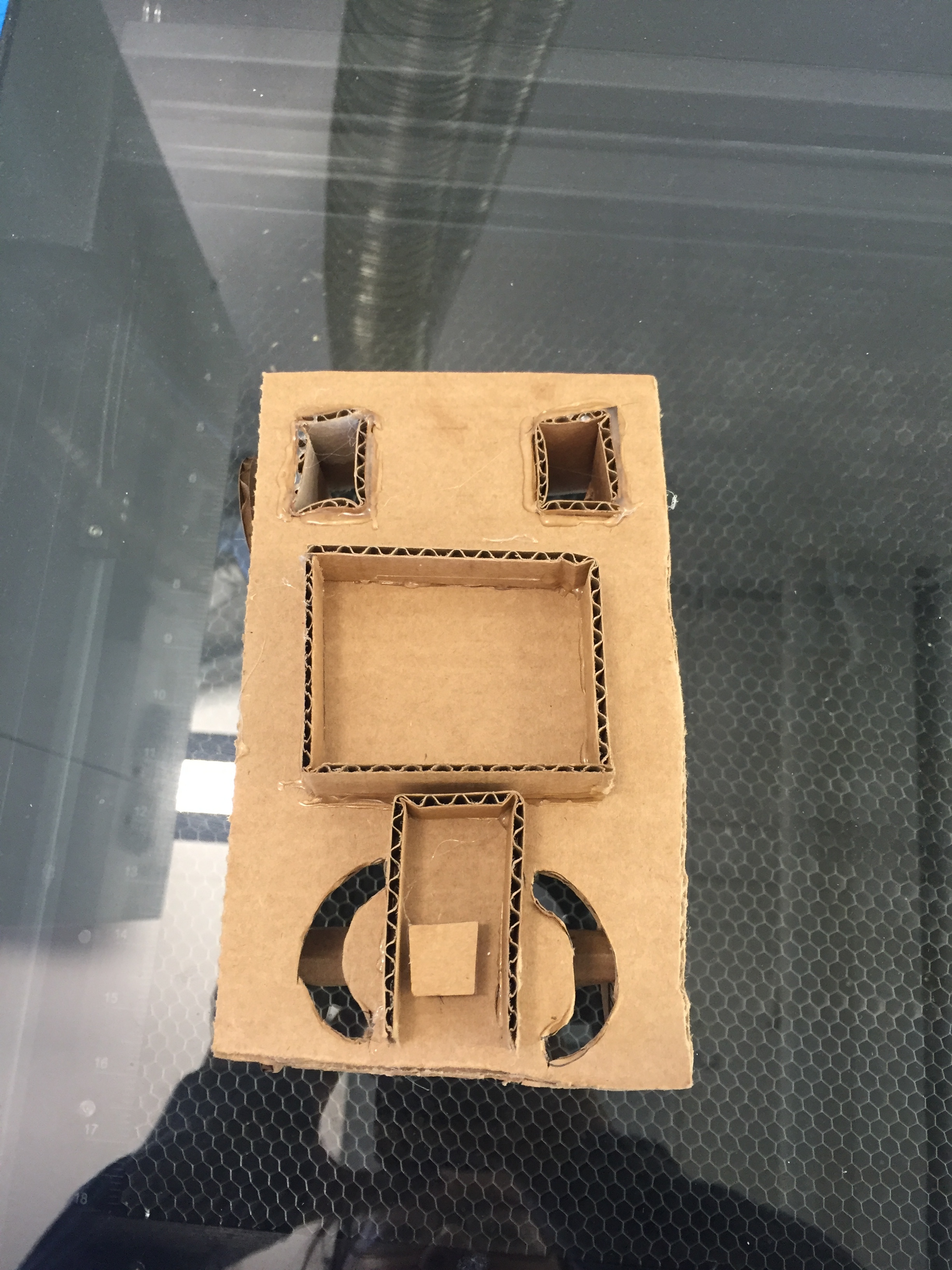
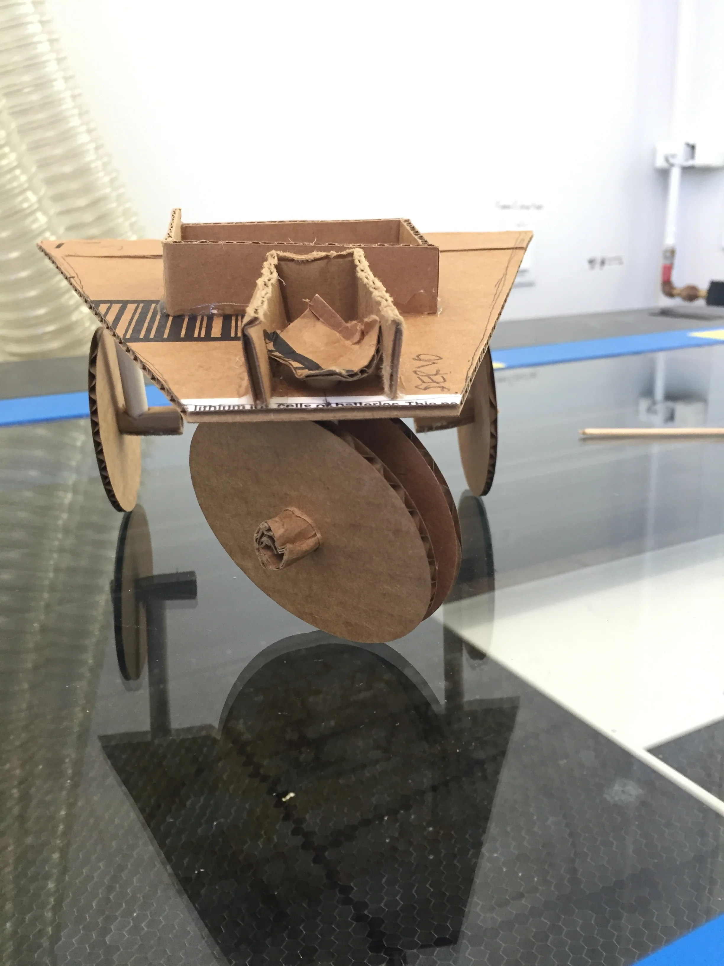
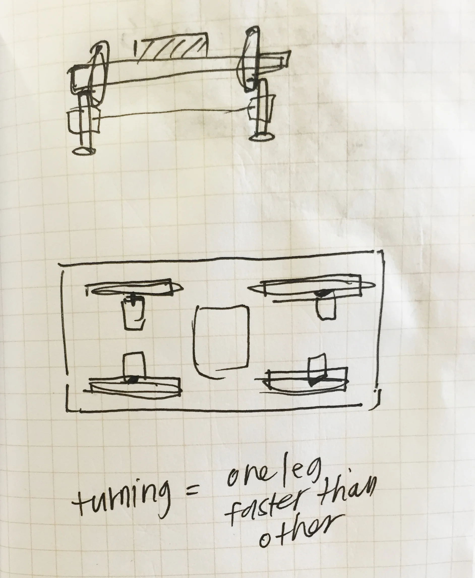
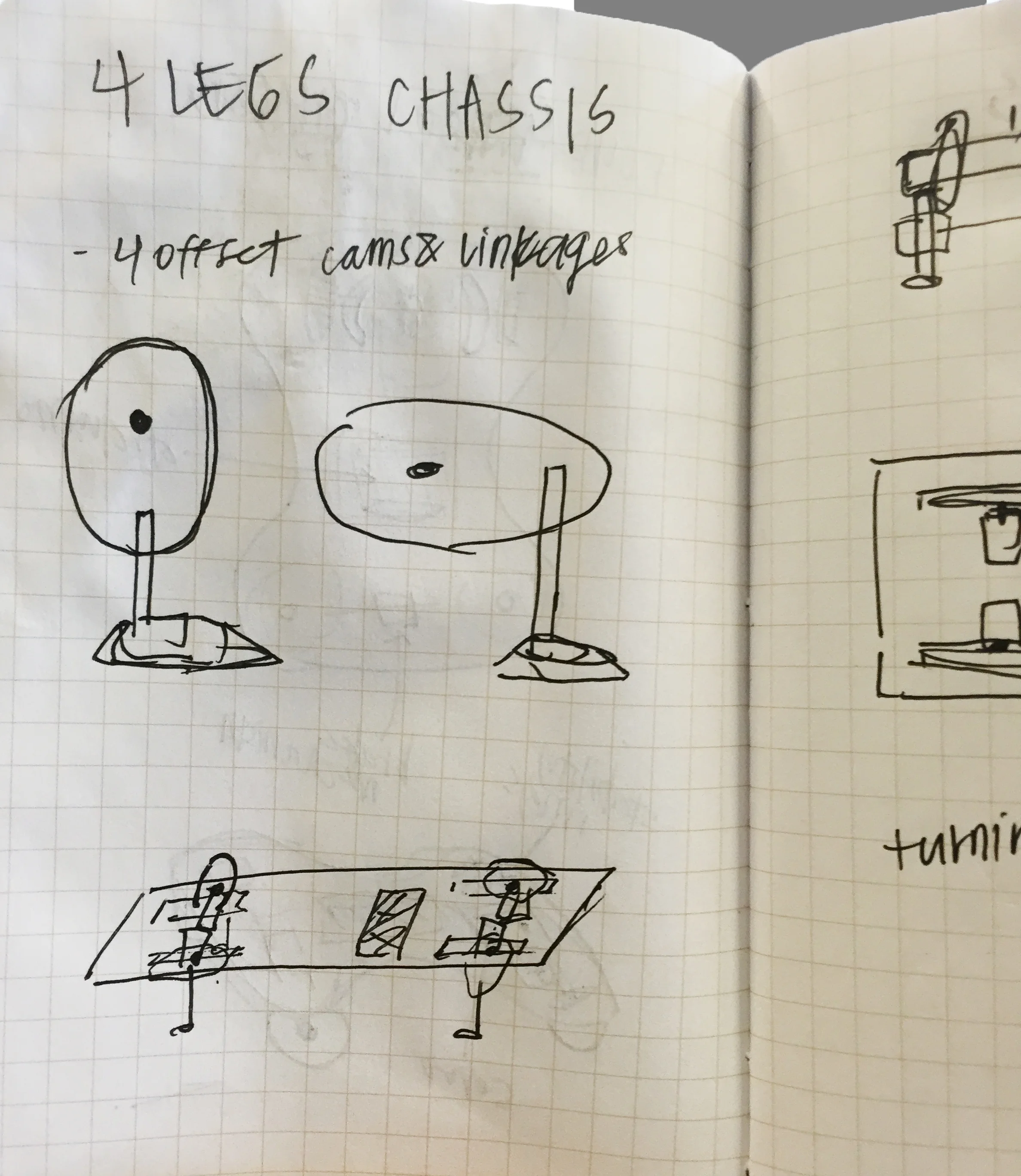
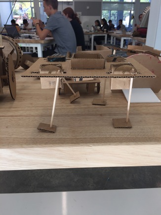
3. Mammalian Chassis Exploration
For my third prototype, I wanted to stray from the traditional vehicle mechanisms and decided to attempt to model four-legged animal movement. Unfortunately it is not particularly sturdy or wieldy, but I am interested in exploring other implementations of the movement. Currently, the prototype uses cams and "linkages" to create the forward stepping movement, but I made a rookie mistake in making the bar holding the cam go all the way to the other end of the opening, effectively blocking the cam from fully rotating. The orientation of the legs on the cams also needs to be better developed.
The Sketch and Cardboard Prototype:
Step 2: Medium Fidelity Mechanism and Chassis Prototype
Out of my three low-fidelity chassis explorations, I decided to go with the Tricycle Style chassis as my final choice. Looking at the materials that I had access to, and my existing knowledge of motors and electronics, it seemed like the most intuitive choice for the first prototype. I designed a laser cut version of my prototype, complete with zip-tie holes for the Arduino, H-Bridge (L298), and "legs".
The Spec:
1 6V Battery Pack for the motors
1 9V Battery Pack for the Arduino power
2 DC Motors & Wheels for the rear wheel power
1 Servo Motor for the front steering wheel
1 L298 Driver/ H-Bridge
1 Sheet Black Matte Acrylic
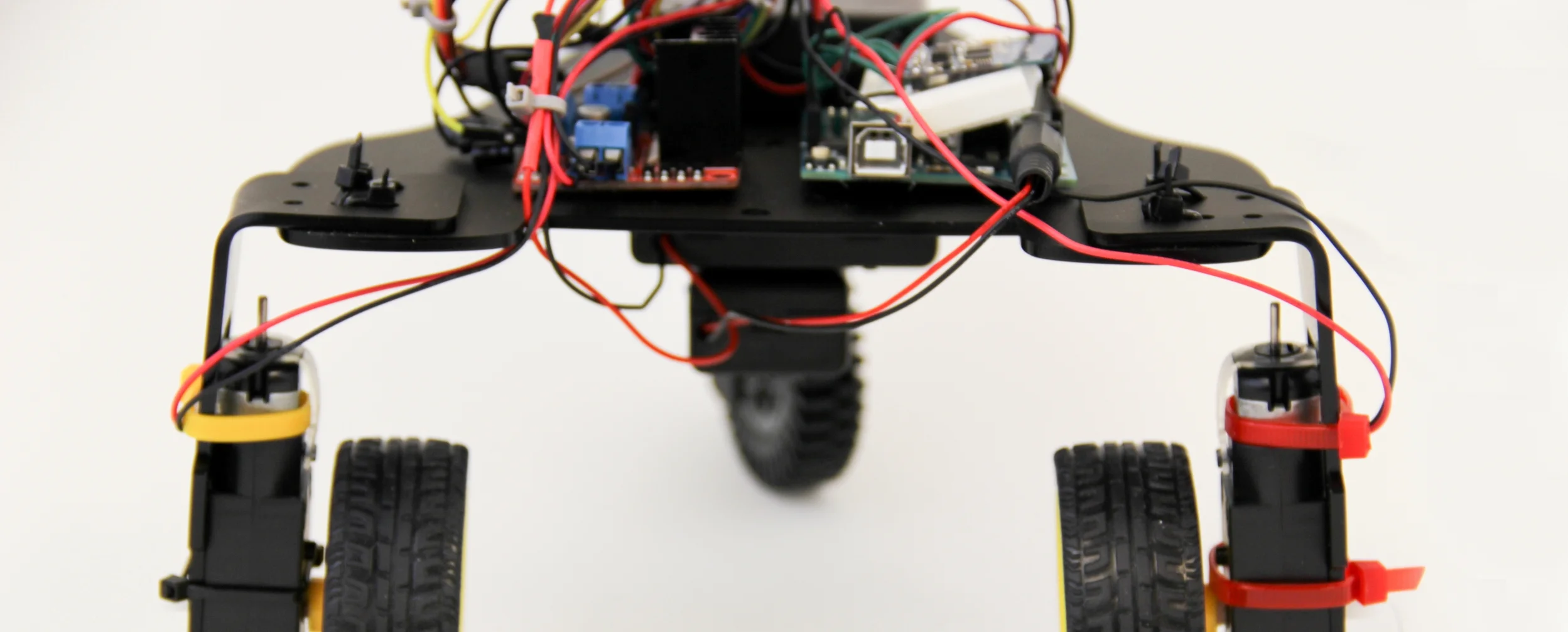
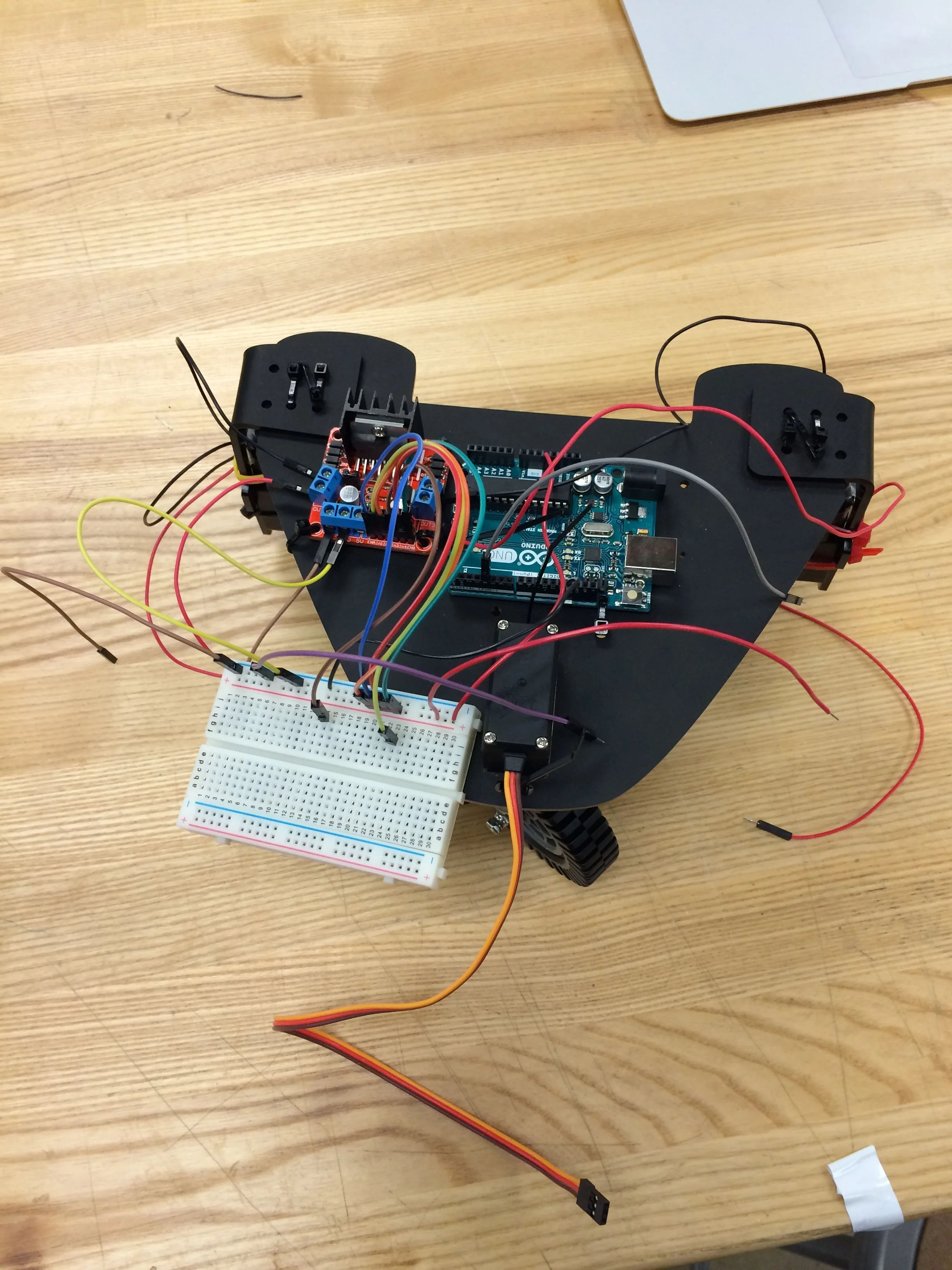
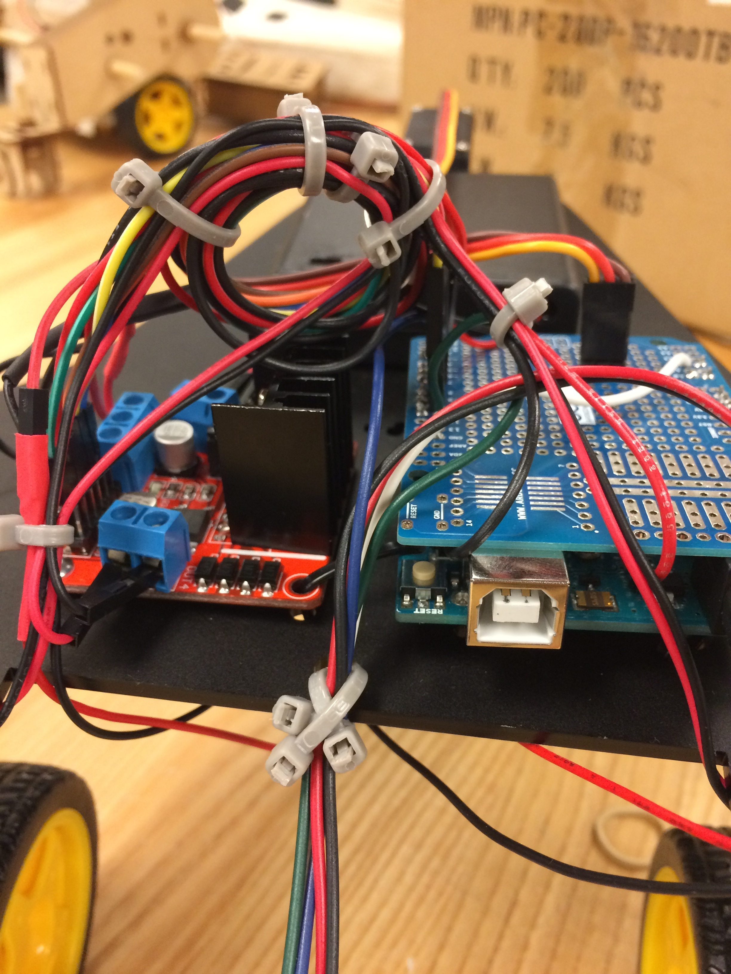
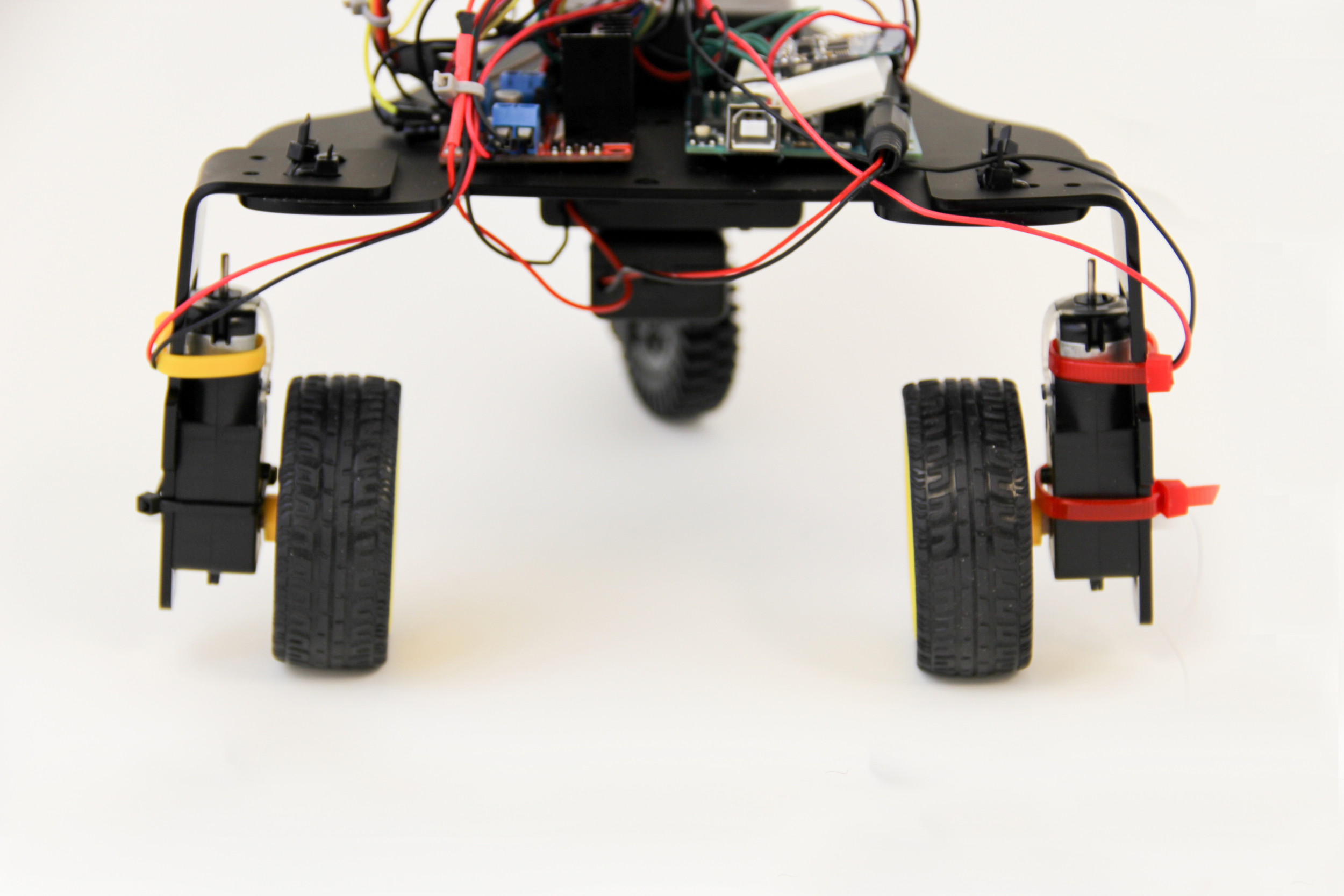
During the week of this stage, I struggled HARD with getting my vehicle to work properly. There were all kinds of weird hardware interactions that caused issues, like Servo pins causing interference to output pins to the H-Bridge. After troubleshooting with instructors, we determined that my servo had broken at some point and that there were power issues with the amount of voltage that was feeding into the H-bridge, making it difficult for the DC motors that were powering the rear wheels to turn. Another hardware issue that I ran into was keeping the voltage pins on the DC motors from breaking-- I ended up having to buy new ones (the yellow ones broke, the black ones are the replacement). Note: to get the acrylic to be curved into the "legs" , I used an acrylic bender to heat the piece, then just used my hands to bend it to the correct angle.
The First Attempt and Mid-Debugging (Please excuse my wire management haha):
Step 3: Iteration
The third week of the project took many, many, many hours.
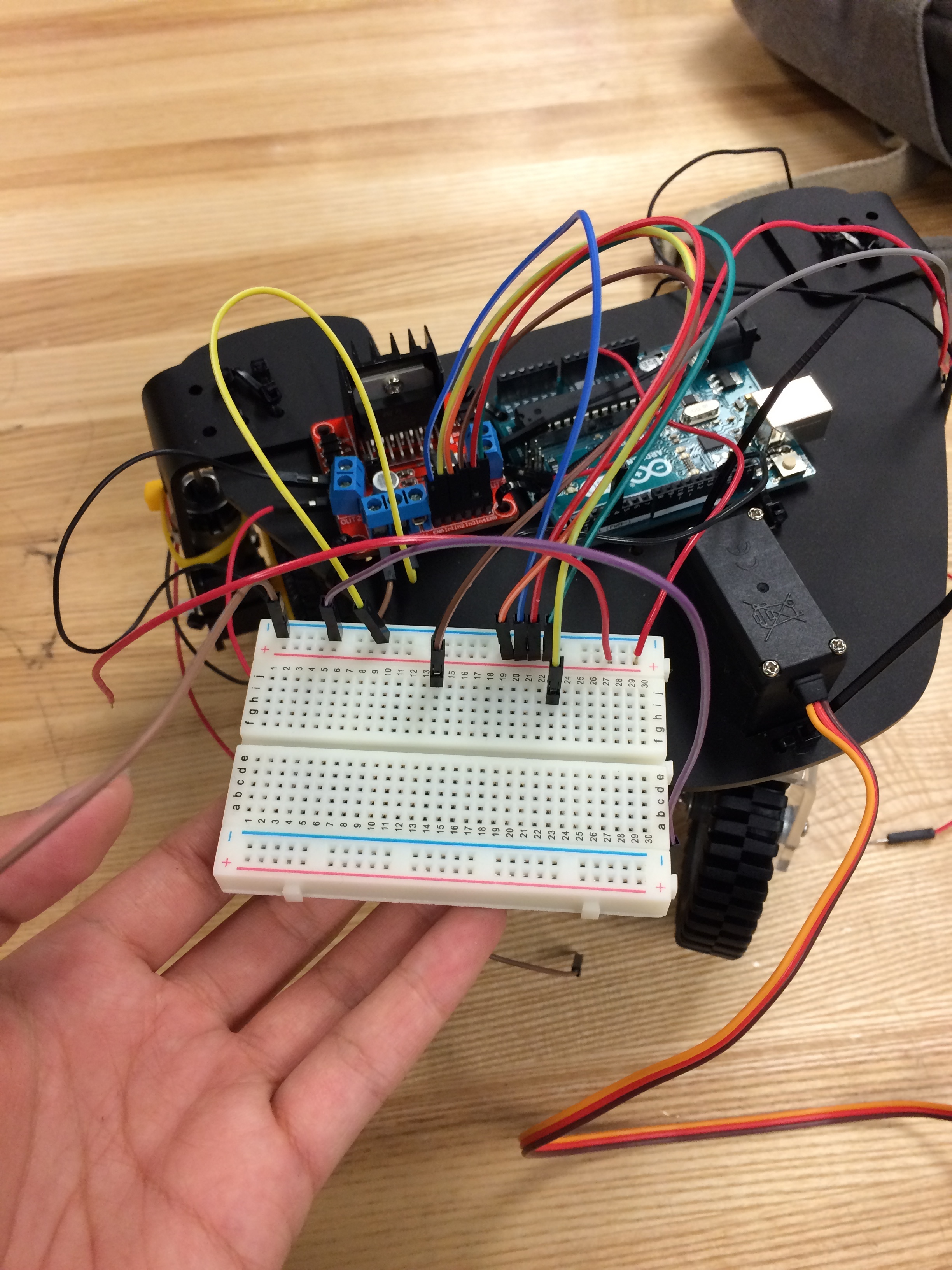
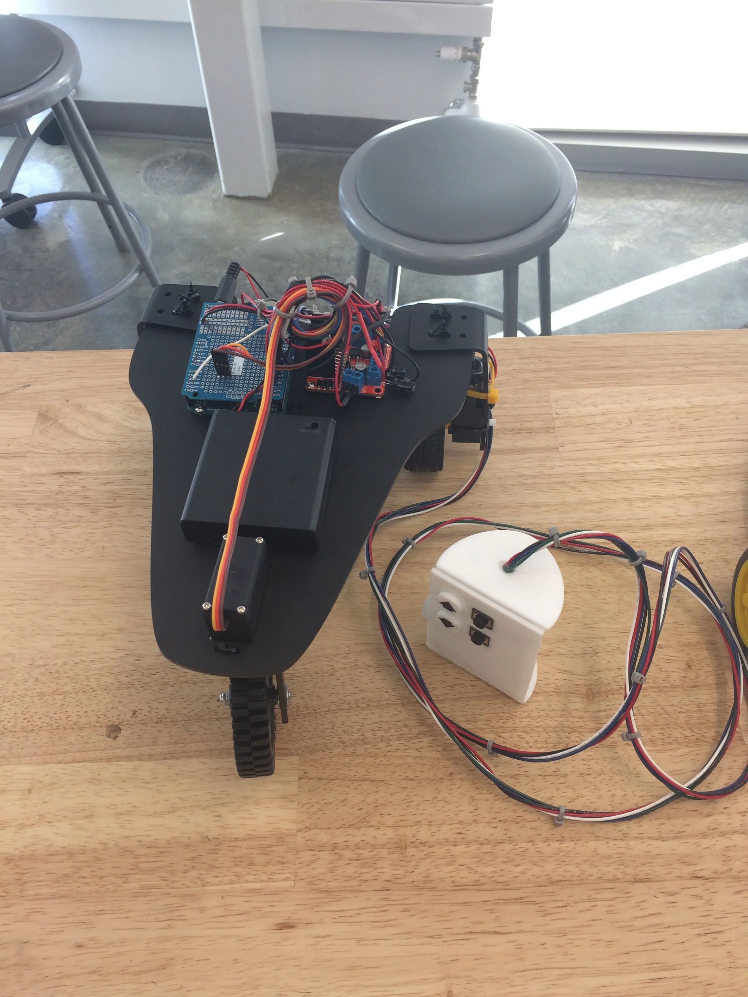
First things first, I had to figure out the problem with my mechanism. After spending an hour in the lab with the instructors, the issue turned out to be a broken servo and a lack of power. To solve this, we replaced the servo, put two battery packs for the motors, and stopped feeding power through the controller. The idea was to simply take inputs from the controller and use software to implement the inputs, rather than directly using analog changes to alter the motion. We first tested this out with a solderless breadboard. To clarify, at this point, there are 12V running through the H-Bridge, so my vehicle was going very fast.
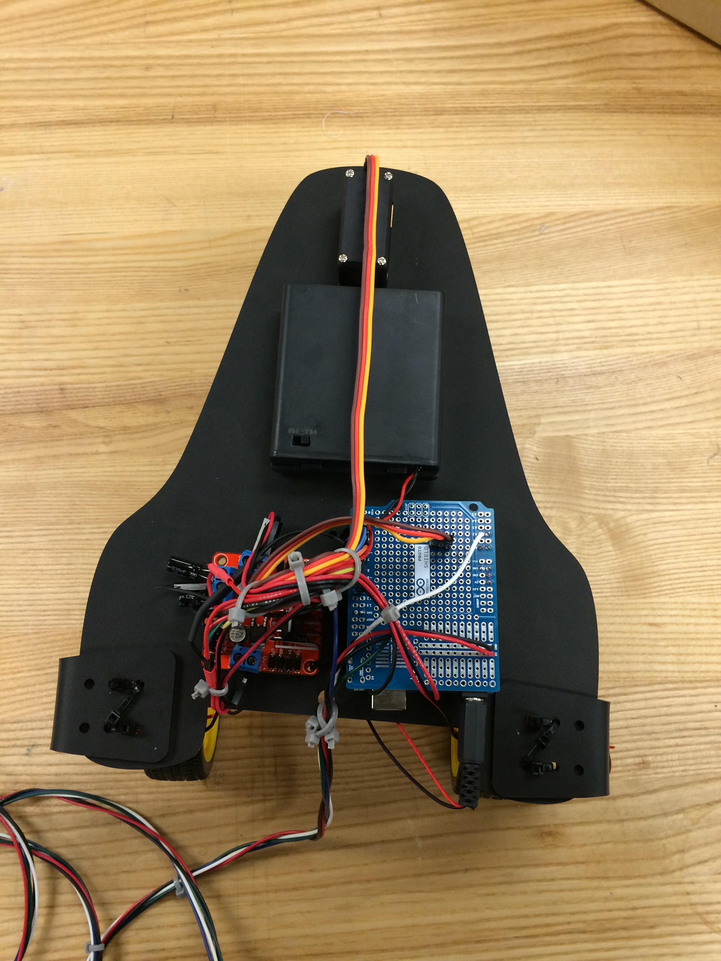
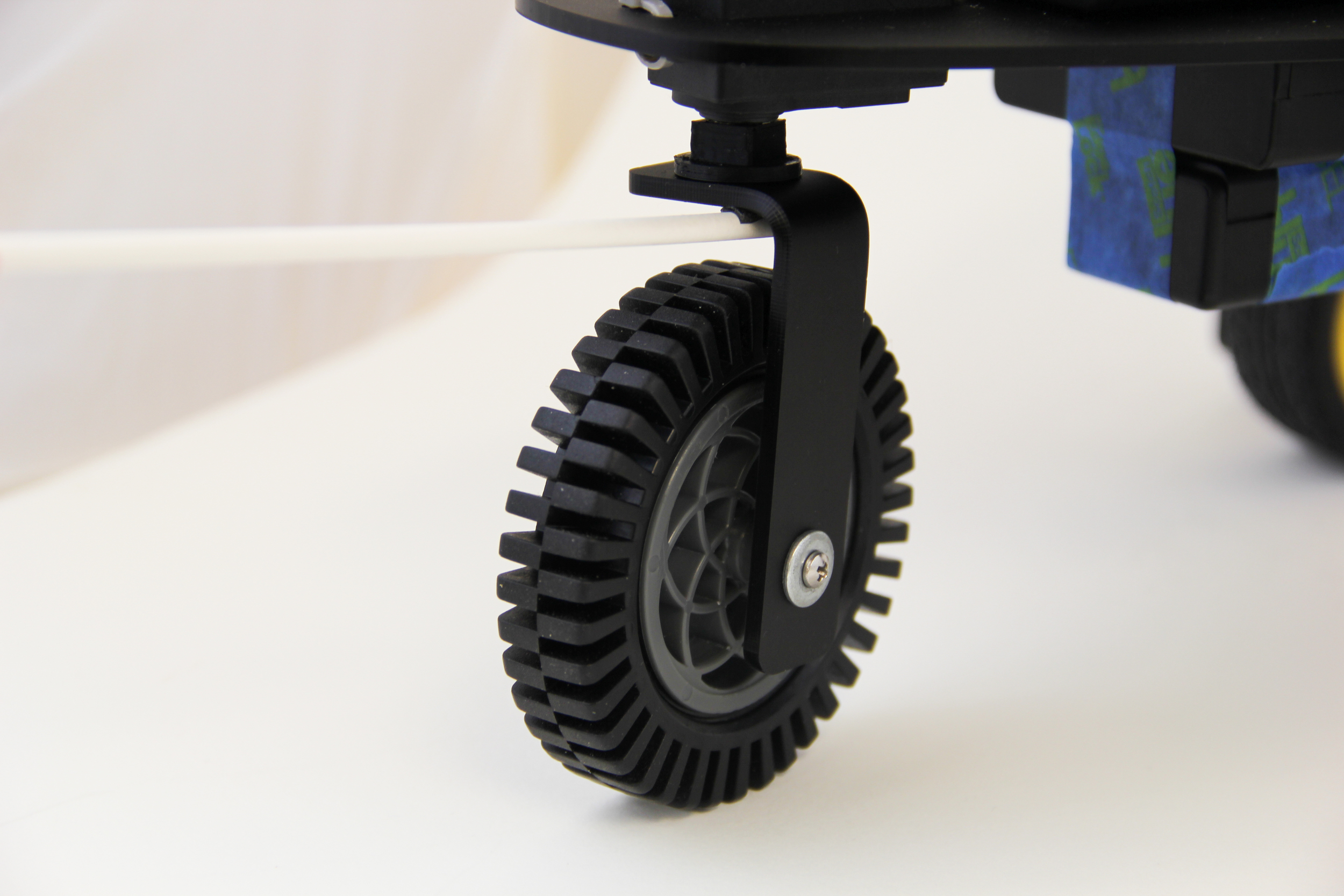
After assembling all of the pieces, it turned out that my chassis was unbalanced, being about as wide as it is long. I recut the chassis and made screw holes for the pieces. I forgot about the fact that I would be flipping the chassis over after cutting, so the holes were reversed. Then, the plugs for the Arduino were on the wrong side. Many holes later, my Arduino and H-bridge were successfully screwed on/zip-tied on. I also ended up recutting the L-shaped arm that held the steering front wheel in place, in order to screw it securely onto the servo to avoid wobbling.
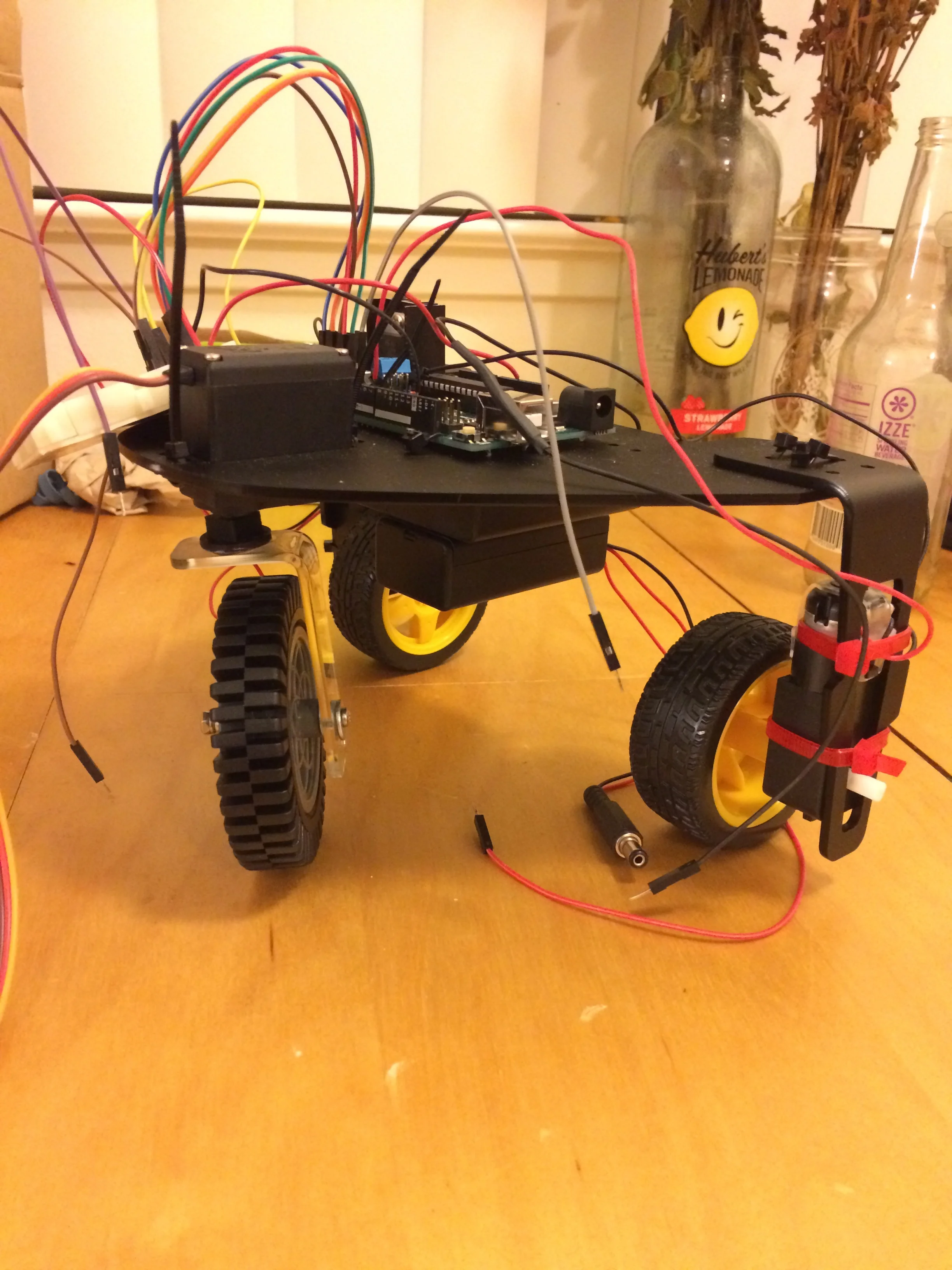
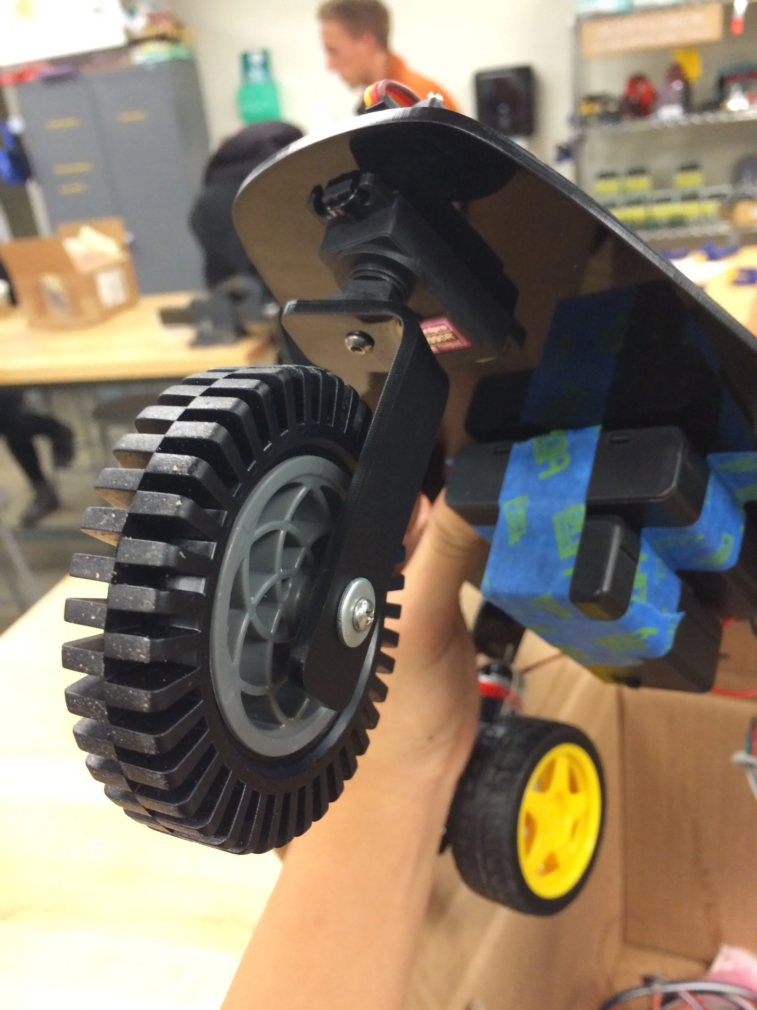
Left: The new chassis design on the finished assembly. || Right: The new L shaped leg screwed into the servo head. || Note: You may be wondering about the blue tape... right before presenting my project, one of the battery pack covers snapped...
For my protoshield, soldering went very smoothly! Everything worked well and the connections were clean. The only problem I encountered was properly cutting the female headers, which I solved by simply filing the cut edges so they sat flush against each other.
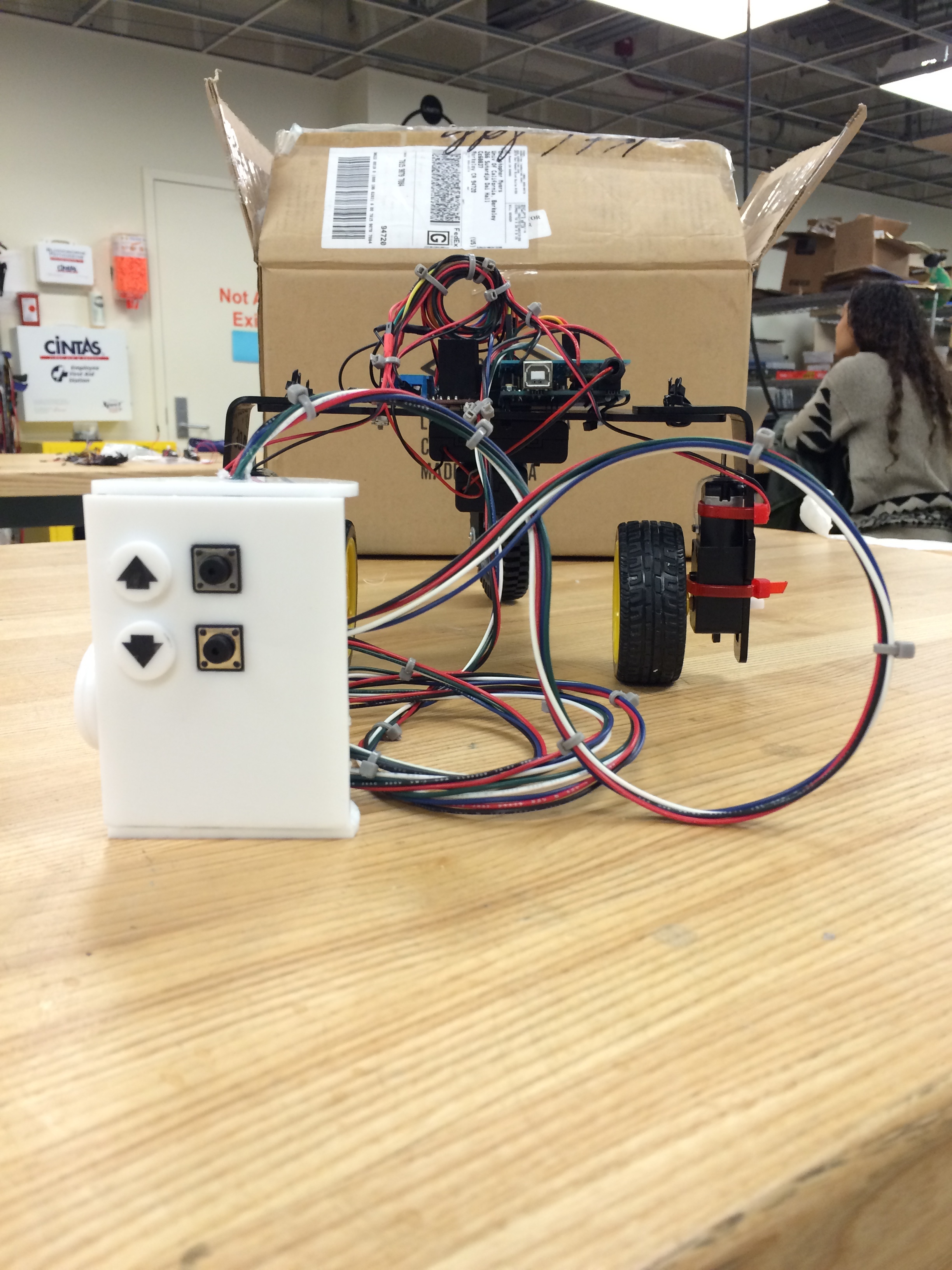
I decided to go with a simple controller shape, forming a hemisphere out of laser cut acrylic. Then, I soldered all the connections to perfboard, super glued pieces into their respective slots, and everything was ready!
Demo Video & Schematic:
Step 4: Iteration 2 - Bluetooth Control
Changing the controller on our concept vehicle from wired to bluetooth controlled from our cell phones sounded straightforward at first, but I ran into a lot of difficult issues.
1. My servo was being powered by 12V, so while it worked with the wired controller, once I switched to bluetooth, it overheated and burned out. This was fixed by attaching the servo to the connection between the two 6V batteries, feeding only 6V through it.
2. Due to a misunderstanding, my servo signal pin ended up being plugged into pin 1 while the program was uploading to the board, unsyncing the USB port. Much debugging later, including trying a new Arduino, I discovered that the problem was that pins 0 and 1 were interfering with the uploading. Tip: upload first, then plug wires in.
3. Pressing start on the buttons caused my motors to start, but not stop. I added in a default case to the switch cases, essentially implementing a power and brake system. The most maneuverable solution will probably be adding in a delay followed by turning the motors off, instead.
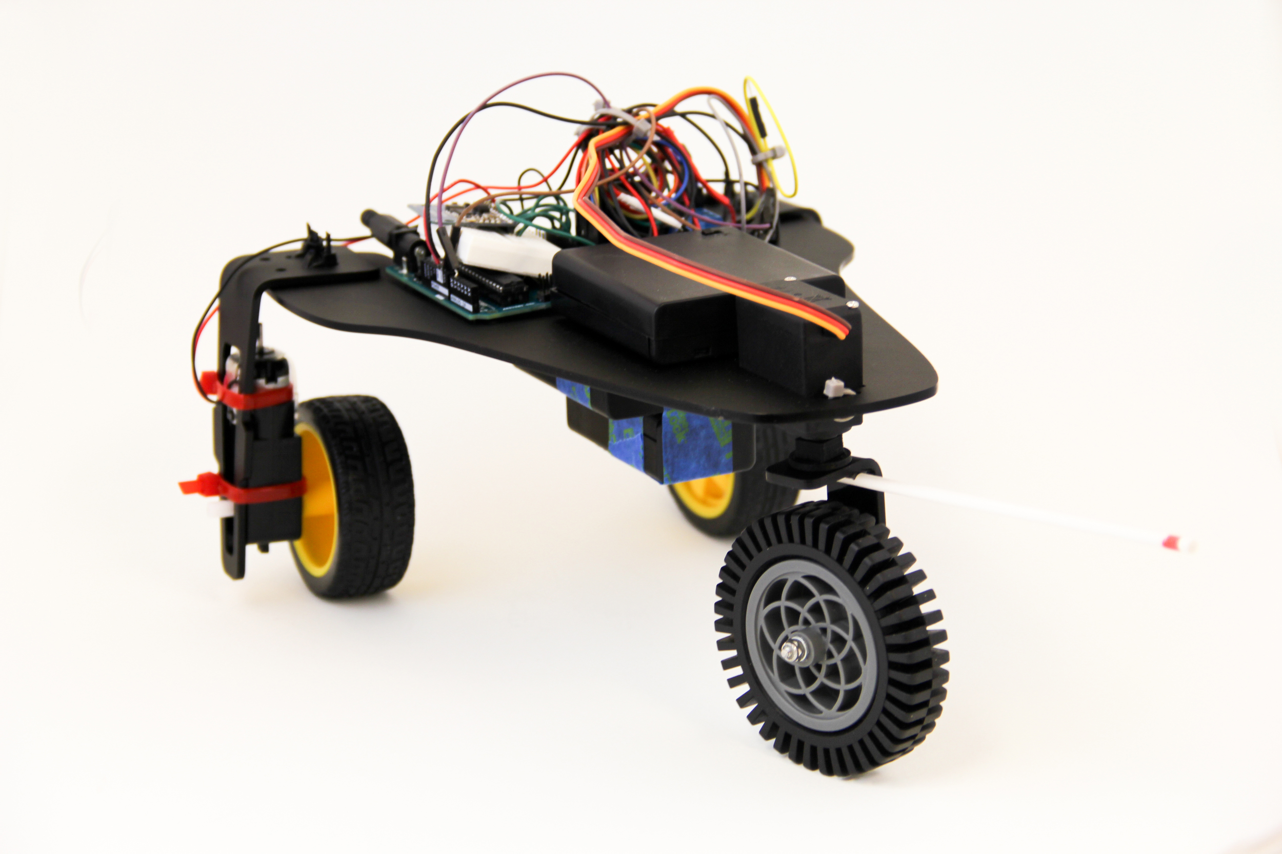
4. It was difficult to see where the front wheel was turning, so I added a hack-y unicorn horn for more visibility.
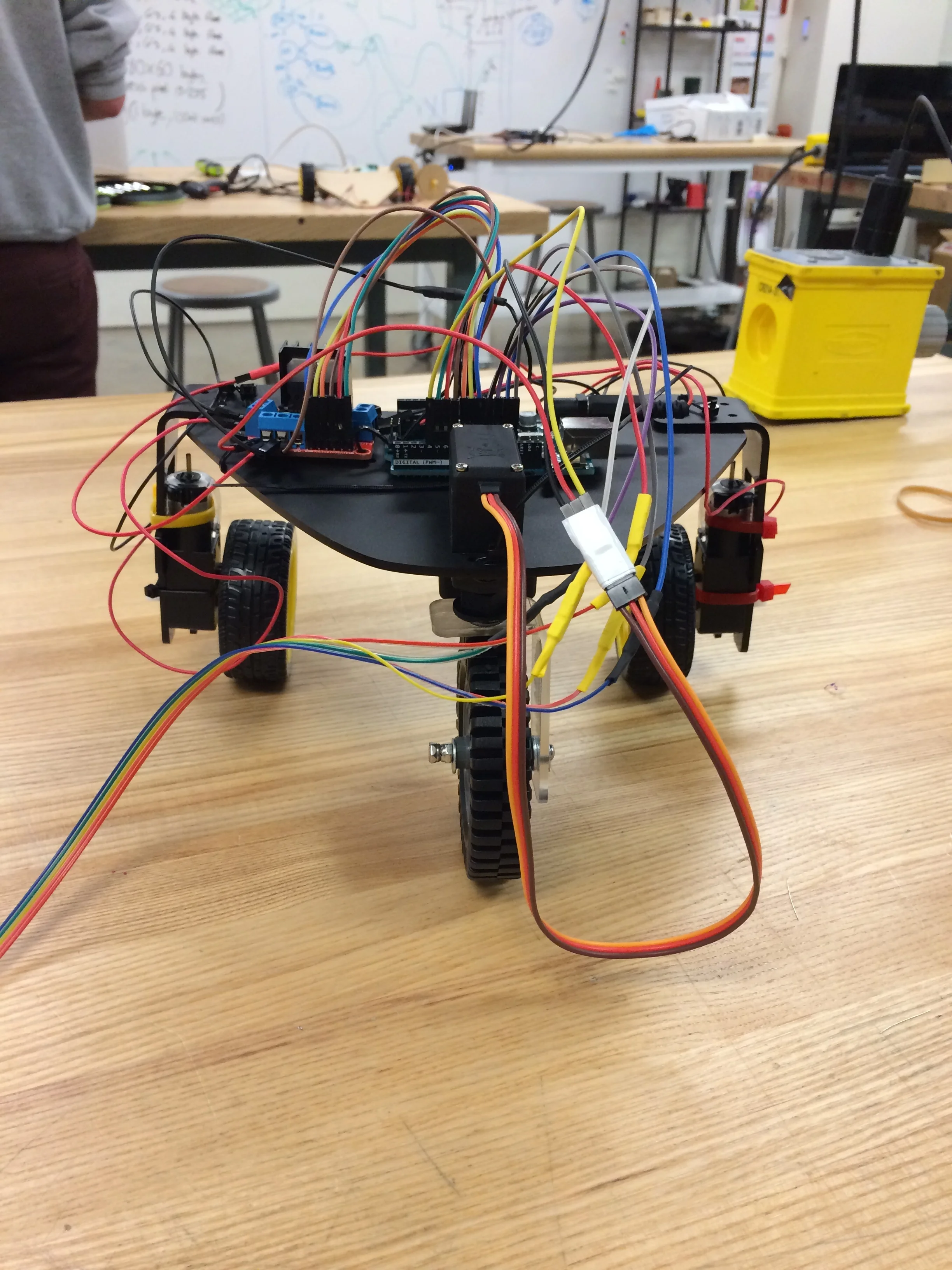
However, it works great now! Again, I'll have to ask that you excuse my wire management, the following video and photos were taken during modification for Step 5.
Step 5: ???
At this point, I'm essentially going back to the beginning of the process to make big changes to my current design. I'm starting with some cardboard prototypes of shells, then i'll move on to adding in the actual mechanism, cutting a new chassis, and adding awesome new things, as well as fixing issues:
- Stabilizing the steering further by using the front steering mechanism from cardboard prototype exploration 2, four wheeled chassis
- Lowering the chassis to avoid flipping when going downhill
- Making the steering easier to visualize, maybe with the unicorn horn in a more elegant fashion, adding lights?
Check back soon for updates!
Page Updated: 12/2/15